
[UPDATED ON NOVEMBER 2024]
A substantial supply of water is an absolute requirement to the tissue paper manufacturing process, and this is the reason why paper mills are located in places rich in this fundamental resource. Water is in fact essential for transporting, treating and distributing the fibers, as well as playing a fundamental role in developing the bonds between the fibers themselves in order to obtain the sheet of paper.
Over the years, great attention has been paid to the environment and to the rationalization of water consumption, with considerable development in the field of process water recycling (cycles closure) made possible by the technological improvement of the plants. This, with the same process water requirements, has led to a significant reduction in both the withdrawal of fresh water from the environment (rivers and wells) and, consequently, in the discharges of waste water.
The use of water and the recovery of white water in tissue paper manufacturing process
In the tissue paper manufacturing process that starts from dry raw material, typically cellulose, the water is first progressively added in the stock preparation phases and subsequently removed in the phases of production of the paper sheet, which take place on the actual paper machine.
In the diagram below, we want to show the quantities of water associated with a unit quantity of fiber for each phase of the production process. The fiber, with a fixed quantity throughout the process, is represented by the small orange rectangles at the bottom, while the rectangles in two different shades of blue identify the quantities of water associated with each single phase. Specifically, the water deriving from the previous phase is represented in light blue, while in dark blue we have the variation in the amount of water that occurs in the phase itself.
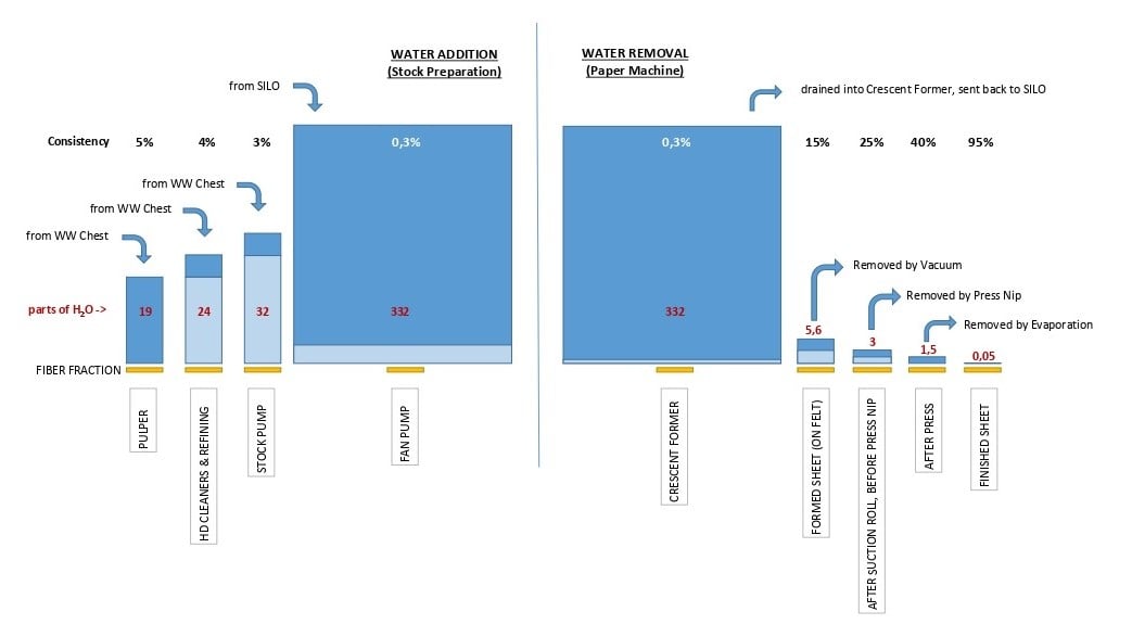
The use of water in tissue paper manufacturing process begins in the stock preparation phase with the pulping of the bales of raw material, by which the cellulose sheets are disaggregated in water in the so-called pulpers. In this phase the proportion between fiber and water, called consistency, is about 5%. This means that 20 parts of water are required for one part of cellulose.
After pulping, the fibrous suspension, called stock, is transferred to temporary storage tanks (dump chests) which have the task of "amortizing" the discontinuities of the plant. Downstream of the dump chests, the stock goes through a cleaning phase by HD Cleaners to separate all the impurities that differ from the fibers in density or morphology. For the correct functioning of this process, the stock must be further diluted to reach a consistency of about 4%, which means adding another 4 parts of water for each part of processed fiber.
At this point the stock is ready for the refining process, a very delicate phase in which the fibers are rubbed to give them volume and anchor points with other fibers, these being fundamental characteristics for their subsequent re-aggregation and the consequent formation of a resistant sheet with all the features required by quality standards.
After refining, the stock is transferred to the machine chest, the last storage chest of the preparation process. Upstream of the machine chest, the stock can be mixed, through the use of a static mixer, with fractions deriving from other processes, such as a second preparation line (in plants with lines dedicated to fibers with different characteristics) or the broke line.
From the machine chest, the stock is sucked in by the stock pump and injected into the inlet of the fan pump, which is the largest pump in the entire plant. The stock ends up in a large conduit through which the fan pump sucks in a large quantity of white water from the so-called silo, a large vertical tubular tank. In fact, in the silo, conveyed by the deaeration channel, the waste waters coming from the forming section of the paper machine are collected. These waters are characterized by the richness of fines (residues of fibers disintegrated during the process) which give them a typical opaque milky white color.
The white waters are substantially those that pass through the wire after depositing on it the fibers that will form the sheet. In the channel and in the silo, the white waters release the air they have trapped during drainage, then they are sucked back by the fan pump, mixed with the fraction of fresh stock and sent back to the machine. White waters go through this cycle (silo - fan pump - paper machine - silo) several times every hour and for this reason it is called white water short circuit.
The function of the white water in the short circuit is exclusively to transport the fibers to the paper machine at a very low consistency, around 0.3% (equal to 300 parts of water for each part of the fiber), which is necessary to obtain the correct sheet formation.
At this point the fan pump pressurizes the stock, an operation necessary to ensure it comes out of the headbox at a speed equal to that of the machine (which can reach over 2000 mpm), and then sends it to the paper machine. Once arrived at its destination, the stock is released through the headbox in the forming section where the fibers, depositing on the wire and separating from the white water, form the sheet of paper.
The transfer and pressurization of these large masses of stock in this phase represent one of the most energy-intensive processes of the entire plant, where small variations in the required consistency can lead to significant variations in the energy consumption of the entire plant. Using solutions such as latest generation headboxes and Crescent Formers capable of producing high quality sheets of paper of the same quality by operating at high consistencies can result in significant energy savings for the entire plant.
In the white water balance, the quantity drained in the forming section and subsequently sent to the silo is greater than that sucked into the silo by the fan pump. The excess of white water in the silo continuously falls and is collected in the white water chest, from which the flows necessary for the functions external to the short circuit are withdrawn, including the aforementioned dilutions that occur in the pulper, in the HD Cleaners and at the exit of the machine chest. Before being placed into the white water tank, the silo overflow is passed through a special filter to recover part of the fibers contained in it.
A part of the white water is instead withdrawn from the chest to be clarified in a flotation unit and collected downstream of this in a clarified water chest, which is used for washing felts and wires, operations in which the presence of fiber or excessive mineral load is unacceptable. In turn, part of the clarified water is withdrawn and filtered through very thick mesh filters to obtain substantially pure water for more delicate uses, such as felts and wires conditioning by means of high pressure sprays. Another part of water, coming from the cooling systems of the hydraulic and lubrication units, is instead conveniently used for the dilution of the chemical additives necessary for the process and for the lubrication of the suction press rolls seals.
Coming back to the paper machine, at the exit of the forming section the newly formed sheet still contains about 6-7 parts of water for each part of fiber, or 15% of "dry weight" (once the sheet is formed the jargon no longer uses the term "consistency"). In the next machine section another fraction of water is eliminated with mechanical processes, first by means of the action exerted by the vacuum in the suction roll and then by means of pressing by forced contact (nip) between a press roll and the Yankee Dryer. Once these two processes have been completed, the proportion between parts of water and parts of fiber is almost equal, that is, little more than one part of water for each part of fiber.
The vacuum through the felt conditioning suction boxes also has a second purpose, namely the recovery of the water contained in the felt of the press downstream of the nip, which is reintroduced into the white water circuit and from here sent to the machine flotation unit for fibers recovering.
The energy associated with the vacuum generation plant is an important fraction of the factory’s total consumption. Having high-efficiency machines for vacuum generation, such as turbine machines (turbo blower vacuum pumps), can lead to considerable and continuous savings on the energy consumption of the entire plant.
At this point in the process, the amount of water remaining in the sheet must be eliminated through physical processes (evaporation) by heating the sheet until it is almost completely dry. This occurs thanks to the use of the Yankee Dryer and the active hood that surrounds it. The water evaporated in this phase is released into the environment in the form of water vapor: this is the "smoke" that is seen coming out of the chimneys of a paper mill.
At the end of the drying process, the sheet contains only 5-6% of water (5 hundredths of a part per each part of fiber), corresponding to a situation of equilibrium with the environment humidity. As we can see, the drying eliminates a relatively very small part of the total water with which the fibers came into contact during the entire process. However, the evaporation process involves a considerable waste of thermal energy, which is supplied by means of steam and hot air generation systems that are among the most complex and largest in the entire plant. These systems consist of the steam boiler, which feeds the Yankee Dryer, and the aerothermal system, which feeds the active hood.
Also in this case, small percentage variations in dryness after the press section can correspond to large variations in energy consumption.
How the waste water treatment works
As we have seen, beyond the small evaporated portion, most of the water is recycled continuously. During the cycles to which it is subjected, the water is progressively enriched with chemicals and electrolytes that tend to "poison it" from the point of view of process requirements. This means that a portion of water must be renewed at each cycle to keep the characteristics of the total within the acceptable limits. In the absence of alternatives, the renewal must be done by withdrawing a certain amount of fresh water from the environment and giving back an approximately equivalent amount in the form of waste water.
The transfer to the environment normally takes place through the collection of the water expelled from the process for plant needs, such as the waste fractions of the HDCs and scrubbers, those collected in the service drainage network in all areas of the plant and the residues of the cyclic washing of the filters. These waters, before being returned to the environment, must be purified in Waste Water Treatment (WWT) plants.
The progressive improvement of these plants (MBBR biological treatment, micro and ultrafiltration) has made it possible in the first place to increasingly safeguard the environment, getting to the point where often the quality of the water discharged into a river is better than that drawn from the river itself. In addition, the aforementioned improvement has paved the way for the reuse of ever larger fractions of this water within the plant in place of the withdrawal of fresh water, "closing" the water cycle more and more. In some plants, more than 90% of closure has already been reached, which in practice means zeroing the discharges and withdrawing from the environment only the amount of water evaporated during the drying process. However, closing the cycle is not free, neither from an energy nor from an investment point of view, and therefore must be carefully evaluated case by case in terms of cost-benefit ratio.
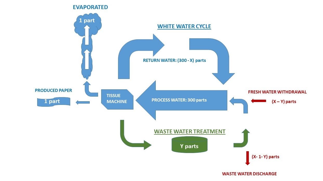
The following diagrams show, in a simplified way, the hydraulic balances of plants with respectively "open" and "closed" water cycles through a Waste Water Treatment plant.
Fig.1 - “Open” water cycle
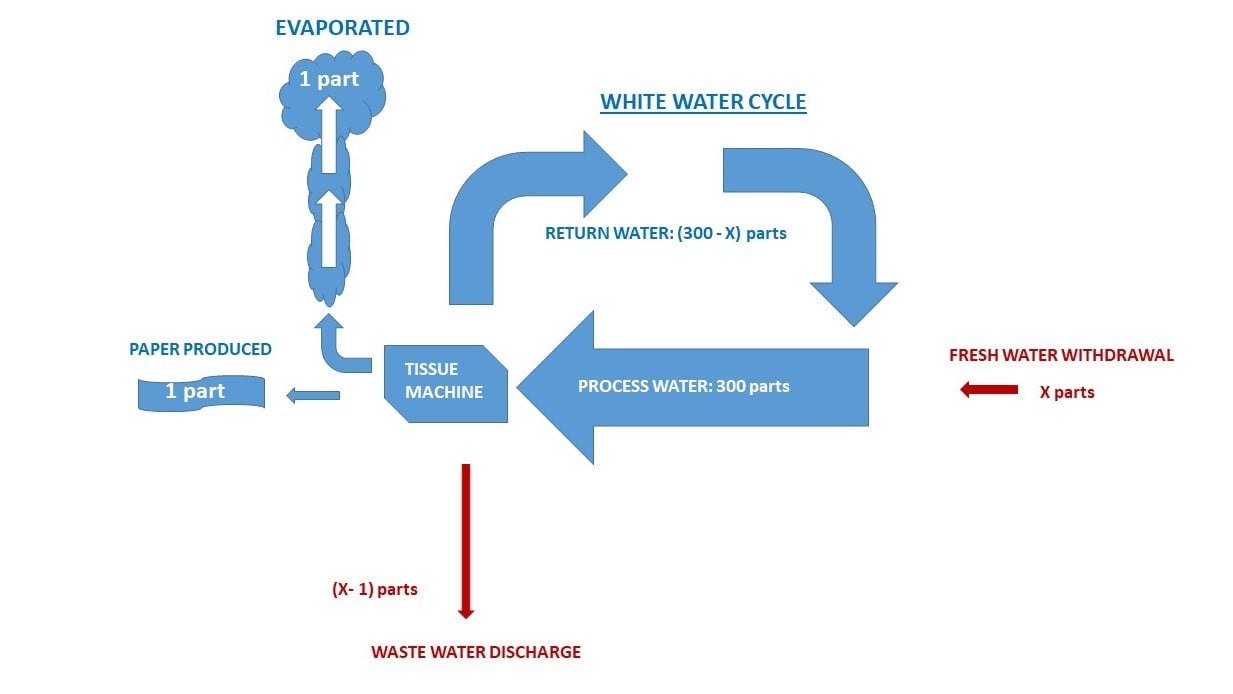
Fig.2 - “Closed” water cycle
If, in addition to water management and the reuse of this important resource, you are also interested in reducing the energy consumption of your tissue plant, download our free eBook “How and where to intervene to reduce the energy consumption of a tissue plant”!
